Small Radius Omni-Grid®
Select another product option
Features
Specifications
Options
Downloads
Features
SMALL RADIUS OMNI-GRID® 75
SMALL RADIUS OMNI-GRID® 75
BELTS THAT RUN SMOOTHER, STRONGER, LONGER
BELTS THAT RUN SMOOTHER, STRONGER, LONGER
SPIRAL

LOTENSION

HYGENIC
TIGHT, 1.1 TURN RATIO FOR SMALL FOOTPRINT OPERATIONS
Small Radius Omni-Grid conveyor belts can negotiate a much tighter turn than regular Omni-Grid belts. In general, the inside radius can be equal to 1.1 times the belt width, making Small Radius Omni-Grid ideal for use in applications where floor space is limited. Small Radius Omni-Grid can turn either left or right, pivoting about a center link.

Proven Reliability
All Ashworth belts are rated for 100,000 cycles versus competition ratings of only 50,000 cycles

Reduced Wear
Patented “protrusion leg” design enables the belt to run smoother with less system wear

Increased Belt Life
Patented coining feature reduces run-in wear and increases belt life
DIRECTION
Does this meet your project needs?
Does this meet your project needs?
Does this meet your project needs?
Let’s get started!
Let’s get started!
Let’s get started!
Specifications
Technical Specifications
Select another product option
| Technical Specifications | Units | Small Radius Omni-Grid® 075 |
|---|---|---|
| Turn Ratio | 1.1-2.0 | |
| Pitch | in. [mm] | 0.75 [19.0] |
| Available Widths: Curve/Spiral | in. [mm] | 12-48 (305-1219) |
| Available Widths: Straight Run | in. [mm] | 12-48 (305-1219) |
| Link Height | in. [mm] | 0.44 [11.1] |
| Rod Diameter/Material | in. [mm] | 0.192 (4.9) Metal |
| Conveying Surface | in. [mm] | Width -1.58 [-40.1] |
| Allowable Tension (Curve/Spiral) | lb. [kg] | 150 [68] at 100,000 cycles (when configured for maximum strength) |
| Allowable Tension (Straight Run) | lb. [kg] | 300 [136] at 100,000 cycles (when configured for maximum strength) |
| Turn Direction | Uni-directional (left or right-must specify direction) | |
| Mode of Turning | Inside edge collapses in turn | |
| Method of Drive | Sprockets driven on links |
Available Sprocket Options
Sprocket Reference

Select another sprocket size
Select a product
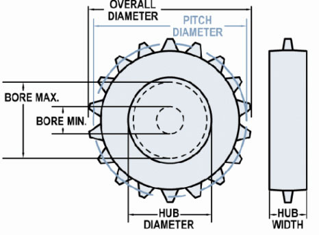
| Nom. Size | Display | Teeth | Pitch Diameter in (mm) | Hub Diameter in (mm) | Bore Min in (mm) | Bore Max in (mm) |
|---|---|---|---|---|---|---|
| 3 | #3-12 Hardened Steel | 12 | 2.9 (73.66) | 2.36 (59.94) | 1 (25.4) | 1.8 (45.72) |
| 3 | #3-12 Hardened Steel | 12 | 2.9 (73.66) | 2.36 (59.94) | 1 (25.4) | 1.8 (45.72) |
| 3 | #3-12 T303 | 12 | 2.9 (73.66) | 2.36 (59.94) | 1 (25.4) | 1.8 (45.72) |
| 3 | #3-12 T303 | 12 | 2.9 (73.66) | 2.36 (59.94) | 0.94 (23.81) | 1.8 (45.72) |
| 3 | #3-12 UHMW | 12 | 2.9 (73.66) | 2.25 (57.15) | 0 | 1.5 (38.1) |
| 3 | #3-16 UHMW | 16 | 3.84 (97.63) | 3 (76.2) | 1.58 (40.01) | 2.13 (54.1) |
| 3 | #3-16 UHMW | 16 | 3.84 (97.64) | 3 (76.2) | 1 (25.4) | 2.13 (54.1) |
| 4 | #4-17 T303 | 17 | 4.08 (103.68) | 3.58 (90.81) | 0 | 2.83 (71.88) |
| 4 | #4-17 UHMW | 17 | 4.08 (103.68) | 3.58 (90.81) | 0.75 (19.05) | 2.58 (65.53) |
| 4 | #4-17 UHMW | 17 | 4.08 (103.68) | 3.58 (90.81) | 1 (25.4) | 2.58 (65.53) |
| 4 | #4-18 T303 | 18 | 4.32 (109.68) | 3.82 (96.9) | 0 | 2.95 (74.93) |
| 4 | #4-18 T303 | 18 | 4.32 (109.68) | 3.82 (96.9) | 1.58 (40.01) | 2.82 (71.63) |
| 5 | #5-19 UHMW | 19 | 4.56 (115.75) | 4.06 (103.05) | 0.75 (19.05) | 2.94 (74.68) |
| 5 | #5-21 T303 | 21 | 5.03 (127.81) | 4.54 (115.27) | 1 (25.4) | 3.55 (90.17) |
| 5 | #5-21 UHMW | 21 | 5.03 (127.81) | 4.54 (115.27) | 1 (25.4) | 3.42 (86.87) |
| 5 | #5-21 UHMW FS | 21 | 4.79 (121.67) | 4.54 (115.32) | 1 (25.4) | 3.42 (86.87) |
| 6 | #6 UHMW FI | 0 | 0 | 6 (152.4) | 0.75 (19.05) | 4.64 (117.86) |
| 6 | #6 UHMW I | 0 | 0 | 6 (152.4) | 0.75 (19.05) | 4.64 (117.86) |
| 6 | #6-25 T303 | 25 | 5.98 (151.99) | 5.5 (139.67) | 0 | 4.39 (111.51) |
| 6 | #6-25 T303 | 25 | 5.98 (151.99) | 5.5 (139.67) | 0.5 (12.7) | 4.39 (111.51) |
| 6 | #6-25 UHMW | 25 | 5.98 (151.99) | 5.5 (139.67) | 0.88 (22.22) | 4.14 (105.16) |
| 6 | #6-26 T303 | 26 | 6.22 (158.04) | 5.73 (145.64) | 0 | 4.62 (117.35) |
| 6 | #6-26 T303 | 26 | 6.22 (158.04) | 5.73 (145.64) | 1.58 (40.01) | 4.62 (117.35) |
| 6 | #6-26 T303 | 26 | 6.22 (158.04) | 5.73 (145.64) | 1.58 (40.01) | 4.62 (117.35) |
| 6 | #6-26 UHMW | 26 | 6.22 (158.04) | 5.73 (145.64) | 1 (25.4) | 4.37 (111) |
| 6 | #6-27 UHMW | 27 | 6.42 (163.12) | 5.97 (151.61) | 0.88 (22.22) | 4.61 (117.09) |
| 8 | #8-34 UHMW | 34 | 8.13 (206.45) | 7.66 (194.46) | 1 (25.4) | 5.93 (150.62) |
3/4" pitch Omni-Grid can use #60 roller chain sprockets modified as follows:
- Face off sprocket such that the overall tooth width is 5/16 (7/94)
- Chamfer corners of the newly machined teeth
* Steel stock sprocket. More available upon request
*Maximum bores provide adequate material thickness for standard keyway. Specify special sized to be used when necessary.
Material Reference
- Acetal - polyoxymethylene plastic
- Celcon - acetal copolymer
- CI - cast iron
- Hardened Steel
- Nylon
- T303 - stainless steel
- T316 - stainless steel
- UMHW - polyethylene plastic
Belt Calculator
No Results
Base Belt Weight
Belt Pitch
Turn Ratio
Belt Strength
Min Filler Roll Diameter
Conveying Surface
Inside Conveying Surface
Outside Conveying Surface
Mesh Opening Size
Open Area Surface
Open Area Thru
Need more detailed information?
Need more detailed information?
Need more detailed information?
Options
Product Options
Omni-Tough Mesh Overlay
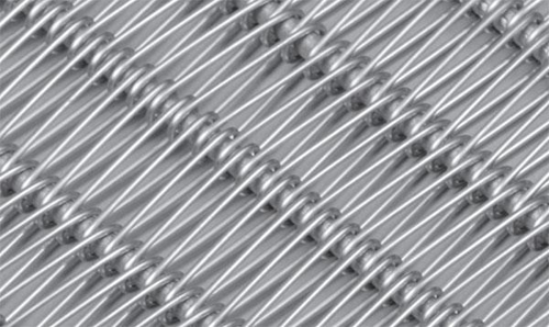
- Stainless steel, spring wire, spiral overlay available in 16 and 17 wire gauges.
- 2-1/2 times stronger and more damage-resistant than conventional wire overlays.
- Provides a flatter surface than standard overlays.
- More resistant to product sticking in freezer application.

Designation
B/U X - Y - Z
- B/U = Balanced or Unilateral Weave
- X = Number of Loops/Foot of Width
- Y = Number of Spirals/Foot of Length
- Z = Wire Gauge of Overlay
Examples:
B30-16-16
U42-16-17
Need more detailed information?
Need more detailed information?
Need more detailed information?
Downloads
Downloads
Technical Bulletins
Installation, Assembly & Maintenance Instructions
Conveyor System Review Form
Illustrations
-
B36-8-16 OG360 WELD 150
-
SROG075 B18 12 16 16
-
SROG075 B18 12 16 17
-
SROG075 B24 12 16 16
-
SROG075 B24 12 16 17
-
SROG075 B30 12 16 16
-
SROG075 B30 12 16 17
-
SROG075 B36 12 16 16
-
SROG075 B36 12 16 17
-
SROG075 B48 12 16 16
-
SROG075 B48 12 16 17
-
SROG075 B54 12 16 16
-
SROG075 B54 12 16 17
-
SROG075 B60 12 16 16
-
SROG075 B60 12 16 17
-
SROG075 ROD ONLY
-
SROG075 U54 12 16 17
-
SROG100 B30 12 12 17
-
SROG100 B36 12 12 17
-
SROG100 B48 12 12 16
-
SROG360 100 B24 12 12 16
-
SROG360 100 B30 12 12 16
-
SROG360 100 B36 12 12 17
-
SROG360 100 U48 12 12 17
Features
SMALL RADIUS OMNI-GRID® 100
SMALL RADIUS OMNI-GRID® 100
BELTS THAT RUN SMOOTHER, STRONGER, LONGER
BELTS THAT RUN SMOOTHER, STRONGER, LONGER
SPIRAL

LOTENSION

HYGENIC
TIGHT, 1.1 TURN RATIO FOR SMALL FOOTPRINT OPERATIONS
Small Radius Omni-Grid conveyor belts can negotiate a much tighter turn than regular Omni-Grid belts. In general, the inside radius can be equal to 1.1 times the belt width, making Small Radius Omni-Grid ideal for use in applications where floor space is limited. Small Radius Omni-Grid can turn either left or right, pivoting about a center link.

Proven Reliability
All Ashworth belts are rated for 100,000 cycles versus competition ratings of only 50,000 cycles

Reduced Wear
Patented “protrusion leg” design enables the belt to run smoother with less system wear

Increased Belt Life
Patented coining feature reduces run-in wear and increases belt life
DIRECTION
Does this meet your project needs?
Does this meet your project needs?
Does this meet your project needs?
Let’s get started!
Let’s get started!
Let’s get started!
Specifications
Technical Specifications
Select another product option
| Technical Specifications | Units | Small Radius Omni-Grid® 100 |
|---|---|---|
| Turn Ratio | 1-2.0 | |
| Pitch | in. [mm] | 1.08 [27.4] |
| Available Widths: Curve/Spiral | in. [mm] | 12-48 (305-1219) |
| Available Widths: Straight Run | in. [mm] | 12-48 (305-1219) |
| Link Height | in. [mm] | 0.50 [12.7] |
| Rod Diameter/Material | in. [mm] | 0.192 (4.9) Metal |
| Conveying Surface | in. [mm] | Width -1.72 [-43.7] |
| Allowable Tension (Curve/Spiral) | lb. [kg] | 150 [68] at 100,000 cycles (when configured for maximum strength) |
| Allowable Tension (Straight Run) | lb. [kg] | 300 [136] at 100,000 cycles (when configured for maximum strength) |
| Turn Direction | Uni-directional (left or right-must specify direction) | |
| Mode of Turning | Inside edge collapses in turn | |
| Method of Drive | Sprockets driven on links |
Available Sprocket Options
Sprocket Reference

Select another sprocket size
Select a product
| Nom. Size | Display | Teeth | Pitch Diameter in (mm) | Hub Diameter in (mm) | Bore Min in (mm) | Bore Max in (mm) |
|---|---|---|---|---|---|---|
| 3 | #3-9 Hardened Steel | 9 | 0 | 2.45 (62.23) | 1 (25.4) | 1.83 (46.48) |
| 3 | #3-9 T303 | 9 | 3.16 (80.26) | 2.46 (62.48) | 1 (25.4) | 1.84 (46.74) |
| 3 | #3-9 T303 | 9 | 3.16 (80.26) | 2.46 (62.48) | 1 (25.4) | 1.84 (46.74) |
| 3 | #3-9 T303 | 9 | 3.16 (80.26) | 2.46 (62.48) | 1.25 (31.75) | 1.84 (46.74) |
| 3 | #3-9 T303 | 9 | 3.16 (80.26) | 2.46 (62.48) | 0.94 (23.81) | 1.84 (46.74) |
| 3 | #3-9 T316 | 9 | 3.16 (80.26) | 2.46 (62.48) | 1.44 (36.51) | 1.84 (46.74) |
| 3 | #3-9 UHMW | 9 | 3.16 (80.26) | 2.53 (64.26) | 1 (25.4) | 1.72 (43.69) |
| 3 | #3-9 UHMW | 9 | 3.16 (80.26) | 2.53 (64.26) | 0 | 1.72 (43.69) |
| 4 | #4 UHMW FI | 0 | 0 | 3.92 (99.57) | 0.75 (19.05) | 2.93 (74.42) |
| 4 | #4 UHMW I | 0 | 0 | 3.92 (99.57) | 0 | 2.93 (74.42) |
| 4 | #4-11 T303 | 11 | 3.83 (97.36) | 3.18 (80.72) | 0 | 2.07 (52.58) |
| 4 | #4-11 T303 | 11 | 3.83 (97.36) | 3.18 (80.72) | 0 | 2.44 (61.98) |
| 4 | #4-12 T303 | 12 | 4.17 (105.97) | 3.54 (89.92) | 0 | 2.8 (71.12) |
| 4 | #4-12 T316 | 12 | 4.17 (105.97) | 3.54 (89.92) | 0 | 2.8 (71.12) |
| 4 | #4-12 UHMW | 12 | 4.17 (105.97) | 3.45 (87.63) | 0.75 (19.05) | 2.46 (62.48) |
| 4 | #4-13 Celcon | 13 | 4.4 (111.76) | 3.9 (99.06) | 1 (25.4) | 2.91 (73.91) |
| 4 | #4-13 CI | 13 | 4.53 (115.09) | 3.91 (99.22) | 0 | 3.04 (77.22) |
| 4 | #4-13 T316 | 13 | 4.53 (115.09) | 3.91 (99.22) | 0 | 3.04 (77.22) |
| 4 | #4-13 UHMW | 13 | 4.53 (115.06) | 3.9 (99.06) | 1 (25.4) | 2.91 (73.91) |
| 5 | #5-15 T303 | 15 | 5.2 (131.95) | 4.58 (116.36) | 0 | 3.59 (91.19) |
| 5 | #5-15 UHMW | 15 | 5.2 (131.95) | 4.58 (116.36) | 2 (50.8) | 3.46 (87.88) |
| 6 | #6 UHMW FI | 0 | 0 | 5.65 (143.51) | 0.75 (19.05) | 4.29 (108.97) |
| 6 | #6 UHMW I | 0 | 0 | 5.65 (143.51) | 0 | 4.29 (108.97) |
| 6 | #6-18 CI | 18 | 6.24 (158.5) | 5.66 (143.67) | 0 | 3.75 (95.25) |
| 6 | #6-18 Nylon | 18 | 6.24 (158.5) | 5.65 (143.51) | 1 (25.4) | 4.54 (115.32) |
| 6 | #6-18 T316 | 18 | 6.24 (158.5) | 5.66 (143.67) | 1 (25.4) | 3.75 (95.25) |
| 6 | #6-18 UHMW | 18 | 6.24 (158.5) | 5.65 (143.51) | 0 | 4.29 (108.97) |
| 6 | #6-18 UHMW FS | 18 | 6.15 (156.16) | 5.65 (143.46) | 0 | 4.29 (108.97) |
| 6 | #6-18 UHMW Product Release | 18 | 6.4 (162.51) | 5.65 (143.46) | 1 (25.4) | 4.29 (108.97) |
| 6 | #6-18 UHMW Split | 18 | 6.24 (158.5) | 5.65 (143.46) | 0 | 4.29 (108.97) |
| 6 | #6-19 T303 | 19 | 6.55 (166.47) | 6.03 (153.21) | 0 | 4.8 (121.92) |
| 6 | #6-19 UHMW | 19 | 6.55 (166.47) | 6.03 (153.21) | 1.18 (30) | 4.67 (118.62) |
| 8 | #8 UHMW FI | 0 | 0 | 7.38 (187.45) | 0.75 (19.05) | 5.89 (149.61) |
| 8 | #8 UHMW I | 0 | 0 | 7.38 (187.45) | 0 | 5.89 (149.61) |
| 8 | #8-23 CI | 23 | 7.41 (188.11) | 7.41 (188.11) | 0 | 5.9 (149.86) |
| 8 | #8-23 CI | 23 | 7.96 (202.18) | 7.41 (188.12) | 0 | 4.75 (120.65) |
| 8 | #8-23 T316 | 23 | 7.96 (202.18) | 7.41 (188.12) | 0 | 4.75 (120.65) |
| 8 | #8-23 T316 | 23 | 7.97 (202.41) | 7.41 (188.12) | 1 (25.4) | 4.75 (120.65) |
| 8 | #8-23 UHMW | 23 | 7.96 (202.18) | 7.39 (187.71) | 1 (25.4) | 5.9 (149.86) |
| 8 | #8-23 UHMW Split | 23 | 7.89 (200.33) | 7.39 (187.63) | 0 | 5.9 (149.86) |
| 10 | #10-31 CI | 31 | 10.72 (272.29) | 10.16 (258.06) | 0 | 8.67 (220.22) |
| 10 | #10-31 T316 | 31 | 10.72 (272.29) | 10.16 (258.06) | 0 | 8.67 (220.22) |
| 10 | #10-31 UHMW | 31 | 10.66 (270.76) | 10.16 (258.06) | 0.99 (25.02) | 8.42 (213.87) |
| 12 | #12-37 UHMW | 37 | 12.74 (323.49) | 12.24 (310.79) | 0.99 (25.02) | 10.49 (266.45) |
* Stock sprockets: UHMWPE, Steel. More available upon request
*Maximum bores provide adequate material thickness for standard keyway. Specify special sized to be used when necessary.
Material Reference
- Acetal - polyoxymethylene plastic
- Celcon - acetal copolymer
- CI - cast iron
- Hardened Steel
- Nylon
- T303 - stainless steel
- T316 - stainless steel
- UMHW - polyethylene plastic
Belt Calculator
No Results
Base Belt Weight
Belt Pitch
Turn Ratio
Belt Strength
Min Filler Roll Diameter
Conveying Surface
Inside Conveying Surface
Outside Conveying Surface
Mesh Opening Size
Open Area Surface
Open Area Thru
Need more detailed information?
Need more detailed information?
Need more detailed information?
Options
Product Options
Omni-Tough Mesh Overlay
- Stainless steel, spring wire, spiral overlay available in 16 and 17 wire gauges.
- 2-1/2 times stronger and more damage-resistant than conventional wire overlays.
- Provides a flatter surface than standard overlays.
- More resistant to product sticking in freezer application.

Designation
B/U X - Y - Z
- B/U = Balanced or Unilateral Weave
- X = Number of Loops/Foot of Width
- Y = Number of Spirals/Foot of Length
- Z = Wire Gauge of Overlay
Examples:
B30-16-16
U42-16-17
Need more detailed information?
Need more detailed information?
Need more detailed information?
Downloads
Downloads
Technical Bulletins
Installation, Assembly & Maintenance Instructions
Conveyor System Review Form
Illustrations
-
B36-8-16 OG360 WELD 150
-
SROG075 B18 12 16 16
-
SROG075 B18 12 16 17
-
SROG075 B24 12 16 16
-
SROG075 B24 12 16 17
-
SROG075 B30 12 16 16
-
SROG075 B30 12 16 17
-
SROG075 B36 12 16 16
-
SROG075 B36 12 16 17
-
SROG075 B48 12 16 16
-
SROG075 B48 12 16 17
-
SROG075 B54 12 16 16
-
SROG075 B54 12 16 17
-
SROG075 B60 12 16 16
-
SROG075 B60 12 16 17
-
SROG075 ROD ONLY
-
SROG075 U54 12 16 17
-
SROG100 B30 12 12 17
-
SROG100 B36 12 12 17
-
SROG100 B48 12 12 16
-
SROG360 100 B24 12 12 16
-
SROG360 100 B30 12 12 16
-
SROG360 100 B36 12 12 17
-
SROG360 100 U48 12 12 17


