Reduced Radius Omni-Grid®
Features
Specifications
Downloads
Features
REDUCED RADIUS OMNI-GRID®
REDUCED RADIUS OMNI-GRID®
TIGHT, 1.6 TURN RADIUS FOR SMALL FOOTPRINT APPLICATIONS
TIGHT, 1.6 TURN RADIUS FOR SMALL FOOTPRINT APPLICATIONS
SPIRAL

LOTENSION

HYGENIC
PROVEN RELIABILITY FOR SPIRAL FREEZING, COOLING, & PROOFING APPLICATIONS
PROVEN RELIABILITY FOR SPIRAL FREEZING, COOLING, & PROOFING APPLICATIONS


Introduced in 1965 and designed to satisfy the need for a lightweight, easy to clean spiral and turn curve belt, the Omni-Grid® Family of stainless-steel components are precision crafted from premium quality stainless steel to exacting standards.
The finish is smooth and burr-free for quick and easy cleaning, maximizing production. Designed with Wear Resistant Links and 6-gauge rods, Reduced Radius Omni-Grid belts have a 1" pitch and feature a tight, 1.6 turn radius.
DIRECTION
APPLICATIONS
MULTIPLE OPTIONS FOR MAXIMUM CAPACITY
Primarily used in the food processing industry for freezing, cooling and proofing, Reduced Radius Omni-Grid stainless steel belts can be manufactured with optional Omni-Tough wire mesh and Special Spirals
STANDARD FEATURES
STANDARD FEATURES

Pigtail Spirals
Reduces wire breakage.
OPTIONAL FEATURES
OPTIONAL FEATURES

Omni-Tough Mesh Overlay
Significant improvement over conventional wire overlay. 2-1/2 times stronger than conventional overlays and resistant to product sticking in freezer applications. Available in various mesh options.

Special Mesh Spirals
A cost-effective solution for adding lane dividers. Special Spirals (patented), used as guard edges, lane dividers and flights, can be added to any Omni-Tough overlay at the time of fabrication. These formed wire spirals are economical and efficient in operation, performing better than stamped metal plates in most applications.
Does this meet your project needs?
Does this meet your project needs?
Does this meet your project needs?
Let’s get started!
Let’s get started!
Let’s get started!
Specifications
Technical Specifications
| Technical Specifications | Units | RROG100 |
|---|---|---|
| Turn Ratio | 1.6 - 2.19 | |
| Pitch | in. [mm] | 1.1 [27] |
| Available Widths: Curve/Spiral | in. [mm] | 12-40 (304.80-1016.00) |
| Available Widths: Straight Run | in. [mm] | 12-40 (304.80-1016.00) |
| Link Height | in. [mm] | 0.50 [13] |
| Rod Diameter/Material | in. [mm] | 0.192 (4.88) Metal |
| Conveying Surface | in. [mm] | -2.54 [-65] |
| Allowable Tension: Curve/Spiral | lb. [kg] | 150.00 [68] |
| Allowable Tension: Straight Run | lb. [kg] | 300.00 [136] |
| Turn Direction | Uni-directional (left or right-must specify direction) | |
| Method of Drive | Sprockets driven on links | |
| Mode of Turning | Inside edge collapses in turn |
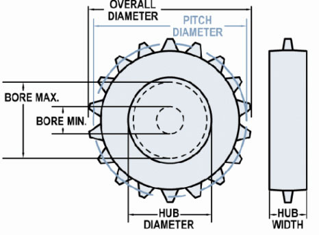
Available Sprocket Options
Sprocket Reference

Select another sprocket size
Select a product
| Nom. Size | Display | Teeth | Pitch Diameter in (mm) | Hub Diameter in (mm) | Bore Min in (mm) | Bore Max in (mm) |
|---|---|---|---|---|---|---|
| 3 | #3-9 Hardened Steel | 9 | 0 | 2.45 (62.23) | 1 (25.4) | 1.83 (46.48) |
| 3 | #3-9 T303 | 9 | 3.16 (80.26) | 2.46 (62.48) | 1 (25.4) | 1.84 (46.74) |
| 3 | #3-9 T303 | 9 | 3.16 (80.26) | 2.46 (62.48) | 1 (25.4) | 1.84 (46.74) |
| 3 | #3-9 T303 | 9 | 3.16 (80.26) | 2.46 (62.48) | 1.25 (31.75) | 1.84 (46.74) |
| 3 | #3-9 T303 | 9 | 3.16 (80.26) | 2.46 (62.48) | 0.94 (23.81) | 1.84 (46.74) |
| 3 | #3-9 T316 | 9 | 3.16 (80.26) | 2.46 (62.48) | 1.44 (36.51) | 1.84 (46.74) |
| 3 | #3-9 UHMW | 9 | 3.16 (80.26) | 2.53 (64.26) | 1 (25.4) | 1.72 (43.69) |
| 3 | #3-9 UHMW | 9 | 3.16 (80.26) | 2.53 (64.26) | 0 | 1.72 (43.69) |
| 4 | #4 UHMW FI | 0 | 0 | 3.92 (99.57) | 0.75 (19.05) | 2.93 (74.42) |
| 4 | #4 UHMW I | 0 | 0 | 3.92 (99.57) | 0 | 2.93 (74.42) |
| 4 | #4-11 T303 | 11 | 3.83 (97.36) | 3.18 (80.72) | 0 | 2.07 (52.58) |
| 4 | #4-11 T303 | 11 | 3.83 (97.36) | 3.18 (80.72) | 0 | 2.44 (61.98) |
| 4 | #4-12 T303 | 12 | 4.17 (105.97) | 3.54 (89.92) | 0 | 2.8 (71.12) |
| 4 | #4-12 T316 | 12 | 4.17 (105.97) | 3.54 (89.92) | 0 | 2.8 (71.12) |
| 4 | #4-12 UHMW | 12 | 4.17 (105.97) | 3.45 (87.63) | 0.75 (19.05) | 2.46 (62.48) |
| 4 | #4-13 Celcon | 13 | 4.4 (111.76) | 3.9 (99.06) | 1 (25.4) | 2.91 (73.91) |
| 4 | #4-13 CI | 13 | 4.53 (115.09) | 3.91 (99.22) | 0 | 3.04 (77.22) |
| 4 | #4-13 T316 | 13 | 4.53 (115.09) | 3.91 (99.22) | 0 | 3.04 (77.22) |
| 4 | #4-13 UHMW | 13 | 4.53 (115.06) | 3.9 (99.06) | 1 (25.4) | 2.91 (73.91) |
| 5 | #5-15 T303 | 15 | 5.2 (131.95) | 4.58 (116.36) | 0 | 3.59 (91.19) |
| 5 | #5-15 UHMW | 15 | 5.2 (131.95) | 4.58 (116.36) | 2 (50.8) | 3.46 (87.88) |
| 6 | #6 UHMW FI | 0 | 0 | 5.65 (143.51) | 0.75 (19.05) | 4.29 (108.97) |
| 6 | #6 UHMW I | 0 | 0 | 5.65 (143.51) | 0 | 4.29 (108.97) |
| 6 | #6-18 CI | 18 | 6.24 (158.5) | 5.66 (143.67) | 0 | 3.75 (95.25) |
| 6 | #6-18 Nylon | 18 | 6.24 (158.5) | 5.65 (143.51) | 1 (25.4) | 4.54 (115.32) |
| 6 | #6-18 T316 | 18 | 6.24 (158.5) | 5.66 (143.67) | 1 (25.4) | 3.75 (95.25) |
| 6 | #6-18 UHMW | 18 | 6.24 (158.5) | 5.65 (143.51) | 0 | 4.29 (108.97) |
| 6 | #6-18 UHMW FS | 18 | 6.15 (156.16) | 5.65 (143.46) | 0 | 4.29 (108.97) |
| 6 | #6-18 UHMW Product Release | 18 | 6.4 (162.51) | 5.65 (143.46) | 1 (25.4) | 4.29 (108.97) |
| 6 | #6-18 UHMW Split | 18 | 6.24 (158.5) | 5.65 (143.46) | 0 | 4.29 (108.97) |
| 6 | #6-19 T303 | 19 | 6.55 (166.47) | 6.03 (153.21) | 0 | 4.8 (121.92) |
| 6 | #6-19 UHMW | 19 | 6.55 (166.47) | 6.03 (153.21) | 1.18 (30) | 4.67 (118.62) |
| 8 | #8 UHMW FI | 0 | 0 | 7.38 (187.45) | 0.75 (19.05) | 5.89 (149.61) |
| 8 | #8 UHMW I | 0 | 0 | 7.38 (187.45) | 0 | 5.89 (149.61) |
| 8 | #8-23 CI | 23 | 7.41 (188.11) | 7.41 (188.11) | 0 | 5.9 (149.86) |
| 8 | #8-23 CI | 23 | 7.96 (202.18) | 7.41 (188.12) | 0 | 4.75 (120.65) |
| 8 | #8-23 T316 | 23 | 7.96 (202.18) | 7.41 (188.12) | 0 | 4.75 (120.65) |
| 8 | #8-23 T316 | 23 | 7.97 (202.41) | 7.41 (188.12) | 1 (25.4) | 4.75 (120.65) |
| 8 | #8-23 UHMW | 23 | 7.96 (202.18) | 7.39 (187.71) | 1 (25.4) | 5.9 (149.86) |
| 8 | #8-23 UHMW Split | 23 | 7.89 (200.33) | 7.39 (187.63) | 0 | 5.9 (149.86) |
| 10 | #10-31 CI | 31 | 10.72 (272.29) | 10.16 (258.06) | 0 | 8.67 (220.22) |
| 10 | #10-31 T316 | 31 | 10.72 (272.29) | 10.16 (258.06) | 0 | 8.67 (220.22) |
| 10 | #10-31 UHMW | 31 | 10.66 (270.76) | 10.16 (258.06) | 0.99 (25.02) | 8.42 (213.87) |
| 12 | #12-37 UHMW | 37 | 12.74 (323.49) | 12.24 (310.79) | 0.99 (25.02) | 10.49 (266.45) |
*Maximum bores provide adequate material thickness for standard keyway. Specify special sized to be used when necessary.
Material Reference
- Acetal - polyoxymethylene plastic
- Celcon - acetal copolymer
- CI - cast iron
- Hardened Steel
- Nylon
- T303 - stainless steel
- T316 - stainless steel
- UMHW - polyethylene plastic
Belt Calculator
No Results
Base Belt Weight
Belt Pitch
Turn Ratio
Belt Strength
Min Filler Roll Diameter
Conveying Surface
Inside Conveying Surface
Outside Conveying Surface
Mesh Opening Size
Open Area Surface
Open Area Thru
Need more detailed information?
Need more detailed information?
Need more detailed information?
Downloads
Downloads
Technical Bulletins
Conveyor System Review Form


