Omni-Grid®
Select another product option
Features
Specifications
Options
Downloads
Features
OMNI-GRID® 075 WELD
OMNI-GRID® 075 WELD
BELTS THAT RUN SMOOTHER, STRONGER, LONGER
BELTS THAT RUN SMOOTHER, STRONGER, LONGER
SPIRAL

LOTENSION

HYGENIC

Proven Reliability
All Ashworth belts are rated for 100,000 cycles versus competition ratings of only 50,000 cycles

Reduced Wear
Patented “protrusion leg” design enables the belt to run smoother with less system wear

Increased Belt Life
Patented coining feature reduces run-in wear and increases belt life
DIRECTION
APPLICATIONS
Specifications
Technical Specifications
Select another product option
| Technical Specifications | Units | OG075 |
|---|---|---|
| Turn Ratio | 2.2-2.5 | |
| Pitch | in. [mm] | 0.75 [19.0] |
| Available Widths: Curve/Spiral | in. [mm] | 6-40 [152-1016] |
| Available Widths: Straight Run | in. [mm] | 6-40 [152-1016] |
| Link Height | in. [mm] | 0.44 [11.1] |
| Rod Diameter/Material | in. [mm] | 0.192 [4.9] Metal |
| Conveying Surface | in. [mm] | Width -2.38 [-60.45] |
| Allowable Tension (Curve/Spiral) | lb. [kg] | 150 [68] at 100,000 cycles (when configured for maximum strength) |
| Allowable Tension (Straight Run) | lb. [kg] | 300 [136] at 100,000 cycles (when configured for maximum strength) |
| Turn Direction | Bi-directional | |
| Mode of Turning | Inside edge collapses in turn | |
| Method of Drive | Sprockets driven on links |
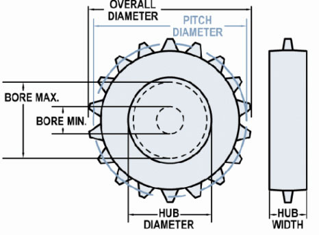
Available Sprocket Options
Sprocket Reference

Select another sprocket size
Select a product
| Nom. Size | Display | Teeth | Pitch Diameter in (mm) | Hub Diameter in (mm) | Bore Min in (mm) | Bore Max in (mm) |
|---|---|---|---|---|---|---|
| 3 | #3-12 Hardened Steel | 12 | 2.9 (73.66) | 2.36 (59.94) | 1 (25.4) | 1.8 (45.72) |
| 3 | #3-12 Hardened Steel | 12 | 2.9 (73.66) | 2.36 (59.94) | 1 (25.4) | 1.8 (45.72) |
| 3 | #3-12 T303 | 12 | 2.9 (73.66) | 2.36 (59.94) | 1 (25.4) | 1.8 (45.72) |
| 3 | #3-12 T303 | 12 | 2.9 (73.66) | 2.36 (59.94) | 0.94 (23.81) | 1.8 (45.72) |
| 3 | #3-12 UHMW | 12 | 2.9 (73.66) | 2.25 (57.15) | 0 | 1.5 (38.1) |
| 3 | #3-16 UHMW | 16 | 3.84 (97.63) | 3 (76.2) | 1.58 (40.01) | 2.13 (54.1) |
| 3 | #3-16 UHMW | 16 | 3.84 (97.64) | 3 (76.2) | 1 (25.4) | 2.13 (54.1) |
| 4 | #4-17 T303 | 17 | 4.08 (103.68) | 3.58 (90.81) | 0 | 2.83 (71.88) |
| 4 | #4-17 UHMW | 17 | 4.08 (103.68) | 3.58 (90.81) | 0.75 (19.05) | 2.58 (65.53) |
| 4 | #4-17 UHMW | 17 | 4.08 (103.68) | 3.58 (90.81) | 1 (25.4) | 2.58 (65.53) |
| 4 | #4-18 T303 | 18 | 4.32 (109.68) | 3.82 (96.9) | 0 | 2.95 (74.93) |
| 4 | #4-18 T303 | 18 | 4.32 (109.68) | 3.82 (96.9) | 1.58 (40.01) | 2.82 (71.63) |
| 5 | #5-19 UHMW | 19 | 4.56 (115.75) | 4.06 (103.05) | 0.75 (19.05) | 2.94 (74.68) |
| 5 | #5-21 T303 | 21 | 5.03 (127.81) | 4.54 (115.27) | 1 (25.4) | 3.55 (90.17) |
| 5 | #5-21 UHMW | 21 | 5.03 (127.81) | 4.54 (115.27) | 1 (25.4) | 3.42 (86.87) |
| 5 | #5-21 UHMW FS | 21 | 4.79 (121.67) | 4.54 (115.32) | 1 (25.4) | 3.42 (86.87) |
| 6 | #6 UHMW FI | 0 | 0 | 6 (152.4) | 0.75 (19.05) | 4.64 (117.86) |
| 6 | #6 UHMW I | 0 | 0 | 6 (152.4) | 0.75 (19.05) | 4.64 (117.86) |
| 6 | #6-25 T303 | 25 | 5.98 (151.99) | 5.5 (139.67) | 0 | 4.39 (111.51) |
| 6 | #6-25 T303 | 25 | 5.98 (151.99) | 5.5 (139.67) | 0.5 (12.7) | 4.39 (111.51) |
| 6 | #6-25 UHMW | 25 | 5.98 (151.99) | 5.5 (139.67) | 0.88 (22.22) | 4.14 (105.16) |
| 6 | #6-26 T303 | 26 | 6.22 (158.04) | 5.73 (145.64) | 0 | 4.62 (117.35) |
| 6 | #6-26 T303 | 26 | 6.22 (158.04) | 5.73 (145.64) | 1.58 (40.01) | 4.62 (117.35) |
| 6 | #6-26 T303 | 26 | 6.22 (158.04) | 5.73 (145.64) | 1.58 (40.01) | 4.62 (117.35) |
| 6 | #6-26 UHMW | 26 | 6.22 (158.04) | 5.73 (145.64) | 1 (25.4) | 4.37 (111) |
| 6 | #6-27 UHMW | 27 | 6.42 (163.12) | 5.97 (151.61) | 0.88 (22.22) | 4.61 (117.09) |
| 8 | #8-34 UHMW | 34 | 8.13 (206.45) | 7.66 (194.46) | 1 (25.4) | 5.93 (150.62) |
Sprockets available in stainless steel, plain steel, and UHMWPE.
UHMWPE material type components have a 150° F (66°C) maximum operation temperature.
Maximum bore sized listed for UHMWPE material is based on 1/2 inch (12.7 mm) of material above keyway.
*Maximum bores provide adequate material thickness for standard keyway. Specify special sized to be used when necessary.
Supports
Support are required at a minimum of 18" apart on load side and 24" maximum on return side. Rollers may also be used. For light loads, support rails may be placed further apart. Consult Ashworth Engineering for assistance.
Material Reference
- Acetal - polyoxymethylene plastic
- Celcon - acetal copolymer
- CI - cast iron
- Hardened Steel
- Nylon
- T303 - stainless steel
- T316 - stainless steel
- UMHW - polyethylene plastic
Belt Calculator
No Results
Base Belt Weight
Belt Pitch
Turn Ratio
Belt Strength
Min Filler Roll Diameter
Conveying Surface
Inside Conveying Surface
Outside Conveying Surface
Mesh Opening Size
Open Area Surface
Open Area Thru
Need more detailed information?
Need more detailed information?
Need more detailed information?
Options
Product Options

Omni-Tough Mesh Overlay
2½ times stronger than conventional
overlays and is resistant to product
sticking in freezer applications

Patented Pigtail Spirals
Reduces wear breakage

Patented Special Mesh Spirals
A cost effective solution for adding
lane dividers or flights
Does this meet your project needs?
Does this meet your project needs?
Does this meet your project needs?
Let’s get started!
Let’s get started!
Let’s get started!
Downloads
Downloads
Technical Bulletins
Conveyor System Review Forms
Illustrations
-
U54-8-17 OG360 WELD 150
-
OG075HD B12 16 16
-
OG075HD B18 16 16
-
OG075HD B18 16 17
-
OG075HD B24 16 16
-
OG075HD B24 16 17
-
OG075HD B30 16 16
-
OG075HD B30 16 17
-
OG075HD B36 16 16
-
OG075HD B36 16 17
-
OG075HD B42 16 16
-
OG075HD B42 16 17
-
OG075HD B48 16 16
-
OG075HD B48 16 17
-
OG075HD B54 16 17
-
OG075HD B60 16 16
-
OG075HD B60 16 17
-
OG075HD B72 16 16
-
OG075HD B72 16 17
-
OG075HD B72 32 16
-
OG075HD MID PITCH ROD
-
OG075HD Rod Only
-
OG100 B60 12 17
-
OG100 B84 22.1 16
-
OG100HD B24 12 17
-
OG100HD B30 12 16
-
OG100HD B30 12 17
-
OG100HD B36 12 16
-
OG100HD B42 12 14
-
OG100SD B42 12 14
-
OMNILITE
Features
OMNI-GRID® 100 WELD
OMNI-GRID® 100 WELD
BELTS THAT RUN SMOOTHER, STRONGER, LONGER
BELTS THAT RUN SMOOTHER, STRONGER, LONGER
SPIRAL

LOTENSION

HYGENIC

Proven Reliability
All Ashworth belts are rated for 100,000 cycles versus competition ratings of only 50,000 cycles

Reduced Wear
Patented “protrusion leg” design enables the belt to run smoother with less system wear

Increased Belt Life
Patented coining feature reduces run-in wear and increases belt life
DIRECTION
APPLICATIONS
Specifications
Technical Specifications
Select another product option
| Technical Specifications | Units | OG100 |
|---|---|---|
| Turn Ratio | 2.2-6.0 | |
| Pitch | in. [mm] | 1.08 [27.4] |
| Available Widths: Curve/Spiral | in. [mm] | 6-40 [152-1016] |
| Available Widths: Straight Run | in. [mm] | 6-40 [152-1016] |
| Link Height | in. [mm] | 0.50 [12.7] |
| Rod Diameter/Material | in. [mm] | 0.192 [4.9] Metal |
| Conveying Surface | in. [mm] | Width -2.44 [-61.98] |
| Allowable Tension (Curve/Spiral) | lb. [kg] | 150 [68] at 100,000 cycles (when configured for maximum strength) |
| Allowable Tension (Straight Run) | lb. [kg] | 300 [136] at 100,000 cycles (when configured for maximum strength) |
| Turn Direction | Bi-directional | |
| Mode of Turning | Inside edge collapses in turn | |
| Method of Drive | Sprockets driven on links |
Available Sprocket Options
Sprocket Reference

Select another sprocket size
Select a product
| Nom. Size | Display | Teeth | Pitch Diameter in (mm) | Hub Diameter in (mm) | Bore Min in (mm) | Bore Max in (mm) |
|---|---|---|---|---|---|---|
| 3 | #3-9 Hardened Steel | 9 | 0 | 2.45 (62.23) | 1 (25.4) | 1.83 (46.48) |
| 3 | #3-9 T303 | 9 | 3.16 (80.26) | 2.46 (62.48) | 1 (25.4) | 1.84 (46.74) |
| 3 | #3-9 T303 | 9 | 3.16 (80.26) | 2.46 (62.48) | 1 (25.4) | 1.84 (46.74) |
| 3 | #3-9 T303 | 9 | 3.16 (80.26) | 2.46 (62.48) | 1.25 (31.75) | 1.84 (46.74) |
| 3 | #3-9 T303 | 9 | 3.16 (80.26) | 2.46 (62.48) | 0.94 (23.81) | 1.84 (46.74) |
| 3 | #3-9 T316 | 9 | 3.16 (80.26) | 2.46 (62.48) | 1.44 (36.51) | 1.84 (46.74) |
| 3 | #3-9 UHMW | 9 | 3.16 (80.26) | 2.53 (64.26) | 1 (25.4) | 1.72 (43.69) |
| 3 | #3-9 UHMW | 9 | 3.16 (80.26) | 2.53 (64.26) | 0 | 1.72 (43.69) |
| 4 | #4 UHMW FI | 0 | 0 | 3.92 (99.57) | 0.75 (19.05) | 2.93 (74.42) |
| 4 | #4 UHMW I | 0 | 0 | 3.92 (99.57) | 0 | 2.93 (74.42) |
| 4 | #4-11 T303 | 11 | 3.83 (97.36) | 3.18 (80.72) | 0 | 2.07 (52.58) |
| 4 | #4-11 T303 | 11 | 3.83 (97.36) | 3.18 (80.72) | 0 | 2.44 (61.98) |
| 4 | #4-12 T303 | 12 | 4.17 (105.97) | 3.54 (89.92) | 0 | 2.8 (71.12) |
| 4 | #4-12 T316 | 12 | 4.17 (105.97) | 3.54 (89.92) | 0 | 2.8 (71.12) |
| 4 | #4-12 UHMW | 12 | 4.17 (105.97) | 3.45 (87.63) | 0.75 (19.05) | 2.46 (62.48) |
| 4 | #4-13 Celcon | 13 | 4.4 (111.76) | 3.9 (99.06) | 1 (25.4) | 2.91 (73.91) |
| 4 | #4-13 CI | 13 | 4.53 (115.09) | 3.91 (99.22) | 0 | 3.04 (77.22) |
| 4 | #4-13 T316 | 13 | 4.53 (115.09) | 3.91 (99.22) | 0 | 3.04 (77.22) |
| 4 | #4-13 UHMW | 13 | 4.53 (115.06) | 3.9 (99.06) | 1 (25.4) | 2.91 (73.91) |
| 5 | #5-15 T303 | 15 | 5.2 (131.95) | 4.58 (116.36) | 0 | 3.59 (91.19) |
| 5 | #5-15 UHMW | 15 | 5.2 (131.95) | 4.58 (116.36) | 2 (50.8) | 3.46 (87.88) |
| 6 | #6 UHMW FI | 0 | 0 | 5.65 (143.51) | 0.75 (19.05) | 4.29 (108.97) |
| 6 | #6 UHMW I | 0 | 0 | 5.65 (143.51) | 0 | 4.29 (108.97) |
| 6 | #6-18 CI | 18 | 6.24 (158.5) | 5.66 (143.67) | 0 | 3.75 (95.25) |
| 6 | #6-18 Nylon | 18 | 6.24 (158.5) | 5.65 (143.51) | 1 (25.4) | 4.54 (115.32) |
| 6 | #6-18 T316 | 18 | 6.24 (158.5) | 5.66 (143.67) | 1 (25.4) | 3.75 (95.25) |
| 6 | #6-18 UHMW | 18 | 6.24 (158.5) | 5.65 (143.51) | 0 | 4.29 (108.97) |
| 6 | #6-18 UHMW FS | 18 | 6.15 (156.16) | 5.65 (143.46) | 0 | 4.29 (108.97) |
| 6 | #6-18 UHMW Product Release | 18 | 6.4 (162.51) | 5.65 (143.46) | 1 (25.4) | 4.29 (108.97) |
| 6 | #6-18 UHMW Split | 18 | 6.24 (158.5) | 5.65 (143.46) | 0 | 4.29 (108.97) |
| 6 | #6-19 T303 | 19 | 6.55 (166.47) | 6.03 (153.21) | 0 | 4.8 (121.92) |
| 6 | #6-19 UHMW | 19 | 6.55 (166.47) | 6.03 (153.21) | 1.18 (30) | 4.67 (118.62) |
| 8 | #8 UHMW FI | 0 | 0 | 7.38 (187.45) | 0.75 (19.05) | 5.89 (149.61) |
| 8 | #8 UHMW I | 0 | 0 | 7.38 (187.45) | 0 | 5.89 (149.61) |
| 8 | #8-23 CI | 23 | 7.41 (188.11) | 7.41 (188.11) | 0 | 5.9 (149.86) |
| 8 | #8-23 CI | 23 | 7.96 (202.18) | 7.41 (188.12) | 0 | 4.75 (120.65) |
| 8 | #8-23 T316 | 23 | 7.96 (202.18) | 7.41 (188.12) | 0 | 4.75 (120.65) |
| 8 | #8-23 T316 | 23 | 7.97 (202.41) | 7.41 (188.12) | 1 (25.4) | 4.75 (120.65) |
| 8 | #8-23 UHMW | 23 | 7.96 (202.18) | 7.39 (187.71) | 1 (25.4) | 5.9 (149.86) |
| 8 | #8-23 UHMW Split | 23 | 7.89 (200.33) | 7.39 (187.63) | 0 | 5.9 (149.86) |
| 10 | #10-31 CI | 31 | 10.72 (272.29) | 10.16 (258.06) | 0 | 8.67 (220.22) |
| 10 | #10-31 T316 | 31 | 10.72 (272.29) | 10.16 (258.06) | 0 | 8.67 (220.22) |
| 10 | #10-31 UHMW | 31 | 10.66 (270.76) | 10.16 (258.06) | 0.99 (25.02) | 8.42 (213.87) |
| 12 | #12-37 UHMW | 37 | 12.74 (323.49) | 12.24 (310.79) | 0.99 (25.02) | 10.49 (266.45) |
Sprockets available in stainless steel, plain steel, and UHMWPE.
UHMWPE material type components have a 150° F (66°C) maximum operation temperature.
Maximum bore sized listed for UHMWPE material is based on 1/2 inch (12.7 mm) of material above keyway.
*Maximum bores provide adequate material thickness for standard keyway. Specify special sized to be used when necessary.
Supports
Support are required at a minimum of 18" apart on load side and 24" maximum on return side. Rollers may also be used. For light loads, support rails may be placed further apart. Consult Ashworth Engineering for assistance.
Material Reference
- Acetal - polyoxymethylene plastic
- Celcon - acetal copolymer
- CI - cast iron
- Hardened Steel
- Nylon
- T303 - stainless steel
- T316 - stainless steel
- UMHW - polyethylene plastic
Belt Calculator
No Results
Base Belt Weight
Belt Pitch
Turn Ratio
Belt Strength
Min Filler Roll Diameter
Conveying Surface
Inside Conveying Surface
Outside Conveying Surface
Mesh Opening Size
Open Area Surface
Open Area Thru
Need more detailed information?
Need more detailed information?
Need more detailed information?
Options
Product Options

Omni-Tough Mesh Overlay
2½ times stronger than conventional
overlays and is resistant to product
sticking in freezer applications

Patented Pigtail Spirals
Reduces wear breakage

Patented Special Mesh Spirals
A cost effective solution for adding
lane dividers or flights
Does this meet your project needs?
Does this meet your project needs?
Does this meet your project needs?
Let’s get started!
Let’s get started!
Let’s get started!
Downloads
Downloads
Technical Bulletins
Conveyor System Review Forms
Illustrations
-
U54-8-17 OG360 WELD 150
-
OG075HD B12 16 16
-
OG075HD B18 16 16
-
OG075HD B18 16 17
-
OG075HD B24 16 16
-
OG075HD B24 16 17
-
OG075HD B30 16 16
-
OG075HD B30 16 17
-
OG075HD B36 16 16
-
OG075HD B36 16 17
-
OG075HD B42 16 16
-
OG075HD B42 16 17
-
OG075HD B48 16 16
-
OG075HD B48 16 17
-
OG075HD B54 16 17
-
OG075HD B60 16 16
-
OG075HD B60 16 17
-
OG075HD B72 16 16
-
OG075HD B72 16 17
-
OG075HD B72 32 16
-
OG075HD MID PITCH ROD
-
OG075HD Rod Only
-
OG100 B60 12 17
-
OG100 B84 22.1 16
-
OG100HD B24 12 17
-
OG100HD B30 12 16
-
OG100HD B30 12 17
-
OG100HD B36 12 16
-
OG100HD B42 12 14
-
OG100SD B42 12 14
-
OMNILITE


